Many of the engines that power Polaris ATVs are liquid-cooled, single-cylinder, SOHC 4-stroke units manufactured by Fuji. The 400, 450 and 500cc engines are nearly identical outside of bore and stroke. The newer 550 engine is updated, but some of these tips still apply. The 570 engine has a DOHC head and is unrelated for this article.
The popularity and sheer production numbers of these ATVs leads to a high demand for service and repair for Fuji engines. There are a few important tips to keep in mind when servicing these engines. This article will give some service specifications and procedures that apply to many of these powerplants, but it is important to have the service manual for the particular vehicle to ensure any minor differences are noted and specific procedures are followed as required by the OEM.
1) To start with, metric tools will be required. Specifically, a set of high-quality, 12-point sockets will be needed if the cylinder head and cylinder must be removed. The large cylinder head bolts require a 14 mm, 12-point socket, and the cylinder bolts require a 12 mm, 12-point socket.
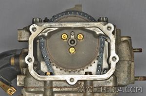
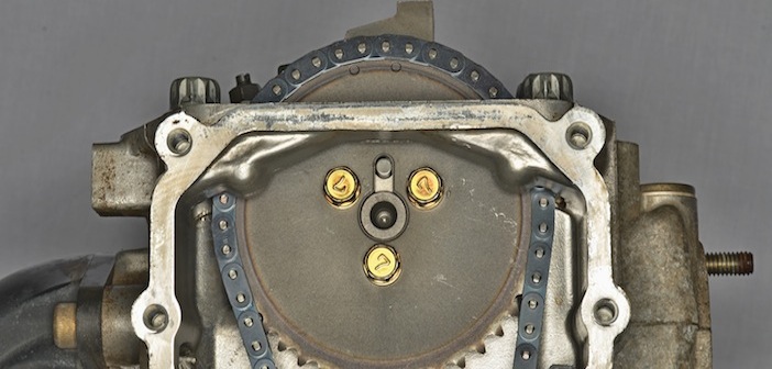
2) The engine should be set to TDC on the compression stroke when checking valve clearance or removing/installing the rocker arms and camshaft. Unlike many engines, there isn’t a quick access plug to be able to rotate the crankshaft by hand with a wrench or socket. Position the crankshaft at TDC on the compression stroke by gradually rotating the crankshaft with the recoil starter. Observe the position of the flywheel through the timing inspection hole and the camshaft sprocket position. The camshaft sprocket locating pin should be pointing up, away from the cylinder, and perpendicular to the cylinder head mating surface at the same time the flywheel TDC mark is lined up with the timing inspection hole.
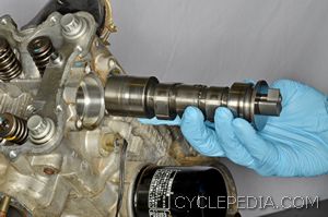
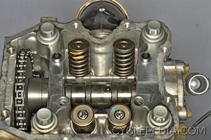
3) Remove the camshaft opposite side of the engine from the camshaft sprocket. Inspect the camshaft, cylinder head and rocker arms for damage, and compare the component measurements and clearances to the factory specifications. Inspect the function of the automatic compression release system. Make sure the weight and return spring for the automatic compression release system are installed correctly when the engine is assembled. Inspect the valve clearance after the camshaft and rocker arms are installed.
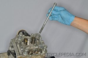
4) Loosen the cylinder head and cylinder bolts a 1/4 turn at a time in a crisscross pattern. On assembly, apply fresh engine oil to the washers, threads and flanges of each large cylinder head bolt. Install the large cylinder head bolts and thread them in by hand. The cylinder head bolts require a multi-step tightening sequence. Tighten the large cylinder head bolts evenly, in a crisscross pattern, according to the stages in the chart above with a high-quality, 14 mm, 12-point socket. Place a mark on the head of the cylinder head bolts to aid in the degree loosening and tightening steps.

5) The crankshaft, balancer shaft and oil pump all have shims that are installed inside the crankcase to set the end play. Measure the bearing depth with a straight edge and the width of the component and old shim with calipers. Subtract the component width and old shim thickness from the total distance between the crankcase bearings. This end play clearance should be .008 – .016 in. (0.2 – 0.4 mm). Replace the shim as needed for each component so the end play is in specification.
Cyclepedia Press LLC authors powersports service manuals, a specification database and training modules to help technicians efficiently service ATVs, motorcycles, scooters and side by sides. Each month Cyclepedia examines real life shop scenarios with recommended tech tips for handling the problems encountered. For more information about Cyclepedia manuals and professional products visit www.cyclepedia.com.