 On-The-Engine Valve Spring Compressor Outline
1. Cylinder Pressurizing Hose
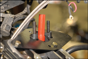
2. Base Plate
3. Threaded Studs (2)
4. Spring Compressor Member
5. Valve Seal Driver
6. Reducer Washer
7. Bolts
8. Nuts (2)
Valve Spring Removal
1. Place transmission in gear with rear wheel firmly placed on a hard working surface and make sure the front wheel is locked.
2. Remove rider’s seat and disconnect negative terminal on battery.
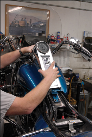
3. Expose top of cylinder head by removing the fuel tank and rocker boxes according to the manufacturer’s procedures.
Note: To access the mounting location for the “Nub” tool remove the complete rocker box assembly including the lower rocker arm cover on 99 and earlier models of Harley Davidson Motorcycles. Remove any other brackets that interfere with the mounting of the Nub valve spring compressor.
4. Remove both spark plugs.
5. Position piston of the cylinder head to be serviced at top dead center.
6. Install cylinder pressurizing hose into spark plug hole (if the 14mm threads are to be used, first remove O-ring at the end of the threaded fitting).
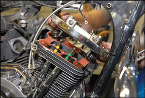
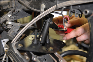
7. Install valve spring compressor base on top of the cylinder head. Position the large hole centered on the valve spring and the two threaded lugs in line with the angle of the valve stem. Fasten the base to the cylinder head using the three 5/16-inch bolts provided (Sportster heads require two 5/16-inch bolts and one 1/4-inch bolt, provided. The 1/4-inch bolt attaches to the right outside hole.) Firmly tighten all hardware.
Note: Do not exceed torque values – 5/16-inch bolt: 15-18ft.lbs. (20.3-24.4 Nm), 1/4-inch bolt: 10-13 ft.lbs. (13.5-176Nm), Exceeding these torque values may result in destruction of cylinder head threads.
8. Install two threaded studs into base. Tighten studs.
9. Pressurize cylinder using shop air (90-120 psi)
10. Install compressing member over studs and spring. If removing conical springs use the reducer washer that is provided.
11. Place the two nuts that are provided over studs and begin evenly rotating the nuts downward a little at a time. Using a ratcheting wrench, compress the valve spring to release the valve spring keepers. Note: If the spring collar and keepers are seized together, apply penetrating lubricant. Then tap the top of the compressing members to break the seal using a plastic or soft brass hammer.
12. Remove the valve spring keepers.
13. Rotate the two nuts evenly upward to remove.
Valve Seal Removal
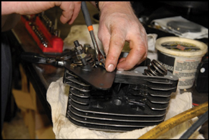
1. Remove valve spring and expose valve seal.
2. Using angular pliers, rotate the valve seal to break its lock on guide. Place nose of pliers under the seal rim. Then using the base of the valve spring compressor as a fulcrum, lift the seal upward along the angle of the valve stem to remove seal.
Valve Seal Installation
1. Remove the threaded stud closest to the operator.
2. Place new seal carefully over valve stem and valve guide. Take caution not to damage the seal on the valve stem retaining groove.
3. Place seal driver over valve stem and onto head of seal.
4. With a small, heavy hammer, strike top of driver until seal is fully seated onto guide.
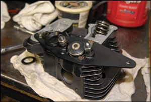
Valve Spring Installation
1. Before installing valve spring compressor base on cylinder head, install the threaded studs into the spring compressor base with the 5/16-inch bolts, and tighten to 15-18ft. lbs. Then follow steps 10 – 13 of valve spring removal in reverse order.
Only the valve stem seal was replaced in this particular case as the customer had issues with lots of smoke coming out of the tall pipe. After finishing up the entire re-assembly of the bike, it was test ridden to confirm the problem was repaired. The job took about an an hour and a half versus four hours for full tear down.